|
|
Creates strings where a wireframe intersects multiple parallel, equally-spaced planes |

Wireframe Multiple Section
To access this dialog:
The Multiple Section dialog is used to create strings along the intersections of parallel, equally-spaced planes, based on either a selected wireframe or preselected wireframe triangle data. The strings will be saved to either a single object, or multiple objects containing a single boundary (using whichever naming Prefix you specify).
Note: This command supports flexible wireframe selection.
Field Details:
Object: either choose a loaded wireframe Object (the default is the current object) or selected wireframe triangle data (Selected triangles). You can select triangle data whilst the dialog is open.
Plane Orientation: provides the tools for defining the orientation of the plane against which the wireframe object will be split.
-
Horizontal: sets the plane to be horizontal (i.e. both Azimuth and Inclination are 0 degrees).
-
North-South: sets the plane to a vertical North-South orientation (i.e. Azimuth is 90 degrees and Inclination is -90 degrees).
-
East-West: sets the plane to a vertical East-West orientation (i.e. Azimuth is 0 degrees and Inclination is -90 degrees).
-
3D Section: if any sections have been defined in the active 3D window, these section planes can be used to generate section strings. Click this button to transfer the azimuth and dip of the section to the relevant fields. If no section data has been defined, this option will be unavailable.
-
Azimuth: sets the azimuth of the plane. Note that this field is automatically updated when either of the top four options are selected.
-
Inclination: sets inclination of the plane. Note that this field is automatically updated when either of the top four options are selected.
Use View Plane: fixes the plane as the current view plane in the 3D window.
Pick Face: click this button, then select a wireframe face in the 3D window. The Azimuth and Inclination will correspond to those of the face and the reference point will have the coordinates of the selected point.
Plane Reference Point: identifies a single point which will fix the plane in space.
-
X: displays or sets the X coordinate (northing) of the reference point.
-
Y: displays or sets the Y coordinate (easting) of the reference point.
-
Z: displays or sets the Z coordinate (elevation) of the reference point.
Section Spacing: sets the separation of the parallel planes starting from the defined plane.
String Output:
-
Single Object Output: selected by default, this check box determines whether a single string object is created, containing multiple string representations of section planes, or if independent string objects (each representing a single plane) are created.
You can output data either within the Current object, an existing wireframe object (pick it from the list) or a new object (type a new name). -
Multiple New Objects: this will output a new string object for each section string that is generated. Each object will start with the defined Prefix (followed by an index number, starting at zero).
-
Section Field: if you are generating a single object as a result of the Multiple Section operation, this object can have an optional, additional field representing the section index that each string entity is related to, within the object. You can use this box to either a) enter a new column definition that will be added to the resulting string object, containing an automatically-incremented section index, relevant to each string entity, b) select an existing field description from the drop-down list (generated from the descriptions found in the original wireframe file) or c) leave the field set to [none] in which case no section index will be output.
OK: close the dialog, create the section strings and save them to a new object(s) named Section(s): wireframe_object_name.
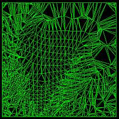
Example
For example, the following wireframe, if 25 meter inter-plane distances were specified:
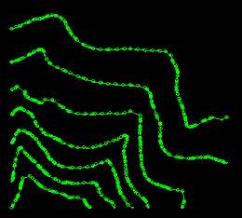
... would become a series of sections (in either a single string object, or multiple objects):